
Semiconductor manufacturing is a complex process, separated into front-end and back-end processes, evolving with technology. It transforms sand into functional chips, demanding precision and quality control.
Overview of the Process
The semiconductor manufacturing process is a remarkably intricate series of steps, from the initial purification of sand to the final packaging of chips. This journey is broadly divided into front-end (FEOL) and back-end (BEOL) manufacturing. FEOL focuses on creating the transistors and active devices on the silicon wafer, utilizing processes like oxidation, photolithography, etching, and ion implantation, alongside deposition techniques such as CVD and PVD.
BEOL then builds upon this foundation, establishing the electrical connections between these devices. This involves metallization, interconnect fabrication, and planarization through Chemical Mechanical Polishing (CMP). Following BEOL, the wafers undergo testing, are diced into individual dies, and encapsulated for protection. Finally, bonding techniques like wire bonding or flip chip are employed to connect the chip to its packaging. Throughout, rigorous testing and data analysis provide feedback to refine manufacturing and assembly, ensuring product quality and reliability.
Importance of Semiconductor Manufacturing
Semiconductor manufacturing is fundamentally critical to modern technology, underpinning nearly every electronic device we use daily. The business of producing semiconductor chips is a complex process, yet its output drives innovation across countless industries – from computing and telecommunications to healthcare and automotive. Without advancements in chip fabrication, progress in these fields would be severely limited.
The ability to create increasingly smaller, faster, and more energy-efficient chips directly impacts the performance and capabilities of electronic systems. Furthermore, robust manufacturing processes are essential for ensuring the reliability and longevity of these devices. Companies like Samsung emphasize data collection and analysis during testing to continually improve product quality. The entire global economy relies on a stable and advanced semiconductor supply chain, making its continued development and optimization paramount for a better future.
Historical Development of Semiconductor Fabrication
The journey of semiconductor fabrication began with the discovery of the transistor in 1947, revolutionizing electronics and paving the way for miniaturization. Early fabrication techniques were rudimentary, relying on manual assembly and discrete components. The late 1950s and 60s saw the development of planar technology, enabling the creation of integrated circuits – multiple transistors on a single chip.
Subsequent decades witnessed exponential advancements driven by Moore’s Law, leading to increasingly complex and densely packed circuits. Photolithography, a key process, evolved significantly, allowing for finer feature sizes. From the initial purification of sand to the final packaging of chips, each step became more refined. Today’s fabrication facilities are incredibly sophisticated, employing advanced techniques like CVD and PVD. This historical progression demonstrates a relentless pursuit of innovation, continually pushing the boundaries of what’s possible in microelectronics.
Front-End Manufacturing (FEOL)
Front-end manufacturing focuses on creating active devices on the wafer, utilizing processes like oxidation, photolithography, etching, and ion implantation to build transistors.
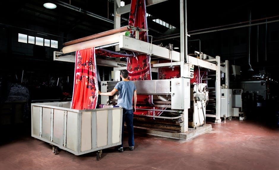
Wafer Fabrication ⏤ From Sand to Silicon
The journey begins with incredibly pure sand, the source material for silicon. This isn’t just any sand; it requires extensive purification to achieve the necessary levels of crystalline perfection. The silicon is then melted and formed into cylindrical ingots, often using the Czochralski process. These ingots are subsequently sliced into thin, circular wafers – the foundation upon which microchips are built.
Achieving this level of purity is paramount, as even minute imperfections can compromise the functionality of the final semiconductor device. The entire process, from the initial purification of sand to the final packaging of chips, is meticulously controlled. Wafers undergo polishing to create a flawlessly smooth surface, essential for the precise layering of materials that follows. This initial stage is absolutely crucial, setting the stage for all subsequent fabrication steps. The quality of the wafer directly impacts yield and performance.
Different materials are also used, and the process is a highly intricate series of steps. The resulting wafers are the canvases for the complex circuitry that powers modern electronics.
Oxidation
Oxidation is a fundamental step in wafer processing, involving the growth of a silicon dioxide (SiO2) layer on the silicon wafer surface. This layer serves multiple critical functions, primarily as an electrical insulator and as a mask during subsequent processes like etching and ion implantation. Thermal oxidation, typically performed at high temperatures, is the most common method, utilizing oxygen or steam as the oxidizing agent.
The thickness of the oxide layer is precisely controlled, as it directly impacts the electrical characteristics of the transistors formed later in the process. This layer is essential for creating the gate dielectric in MOSFETs, influencing device performance. The process is a highly intricate series of steps, requiring careful monitoring of temperature, time, and gas flow.
Following oxidation, a layer of light-blocking film is created, matching the design of the desired circuits. This process prepares the wafer for the next crucial step: photolithography, where patterns are transferred onto the oxide layer.
Photolithography
Photolithography is a pivotal process in semiconductor fabrication, responsible for transferring intricate circuit patterns onto the silicon wafer. It begins with coating the wafer with a light-sensitive material called photoresist. A mask, containing the desired circuit design, is then aligned over the wafer, and ultraviolet (UV) light is shone through it.
The UV light alters the chemical structure of the exposed photoresist, making it either soluble (positive resist) or insoluble (negative resist) in a developer solution. Following exposure, the developer removes the altered photoresist, leaving behind a patterned layer that mirrors the mask’s design. This leaves behind a layer of light-blocking film that matches the design of the desired circuits.
Precise alignment and control of exposure parameters are crucial for achieving high resolution and accurate pattern transfer. This process is a highly intricate series of steps, demanding extreme precision.
Etching Processes

Etching is a critical step following photolithography, used to selectively remove material from the wafer, defining the circuit patterns. It’s essentially the process of “carving” the desired structures into the silicon. Two primary etching methods are employed: wet etching and dry etching.
Wet etching utilizes liquid chemical solutions to dissolve the unprotected material. While simpler and more cost-effective, it can be less precise and isotropic, meaning it etches in all directions. Dry etching, conversely, employs plasma or reactive gases to remove material, offering greater anisotropy – etching primarily downwards – and improved control.
Following photolithography, the unwanted photoresist is removed by an etching process. The choice between wet and dry etching depends on the specific material being etched, the desired feature size, and the required precision. Both methods require careful control of parameters like temperature, pressure, and gas composition to achieve optimal results.
Ion Implantation
Ion implantation is a crucial process for introducing dopant atoms – impurities like boron or phosphorus – into the silicon wafer, modifying its electrical conductivity. This precisely controlled doping is fundamental to creating the transistors and other semiconductor devices. It involves accelerating ions to high energies and directing them towards the wafer surface.
The depth of ion penetration, and therefore the location of the dopant atoms, is determined by the ion’s energy. The concentration of dopants is controlled by the ion beam current and duration. Following implantation, an annealing step is essential to repair any crystal damage caused by the ion bombardment and to activate the dopants, allowing them to contribute to conductivity.
This technique allows for very precise control over dopant profiles, enabling the creation of complex device structures. It’s a cornerstone of modern semiconductor fabrication, vital for achieving the desired electrical characteristics of the final chips.
Deposition Techniques (CVD, PVD)
Deposition techniques are essential for building up thin films on the wafer surface, creating the layers needed for transistors, insulators, and interconnects. Two primary methods are Chemical Vapor Deposition (CVD) and Physical Vapor Deposition (PVD). CVD involves reacting gaseous precursors on the wafer, forming a solid film – offering excellent conformality.
PVD, conversely, involves physically ejecting material from a target and depositing it onto the wafer. Sputtering is a common PVD technique, utilizing ion bombardment. Both CVD and PVD offer different advantages; CVD excels at complex compositions and conformal coverage, while PVD is often simpler and suitable for metals.
The choice between CVD and PVD depends on the material being deposited and the desired film properties. Precise control of deposition parameters – temperature, pressure, gas flow – is crucial for achieving the required film thickness, composition, and quality, impacting device performance significantly.

Back-End Manufacturing (BEOL)
Back-End-Of-Line (BEOL) focuses on metallization and interconnects, building the wiring that connects transistors. This involves processes like CMP and passivation for reliable circuits.
Metallization and Interconnects
Metallization and interconnects represent a critical stage within Back-End-Of-Line (BEOL) processing, establishing the electrical pathways between the millions of transistors fabricated on a chip. This involves depositing conductive materials, traditionally aluminum but increasingly copper due to its superior conductivity, to form a complex network of wires. These layers are meticulously patterned using photolithography and etching techniques, mirroring the intricate circuit design.
Multiple layers of interconnects are built up, separated by insulating materials (dielectrics), creating a multi-dimensional wiring system. The goal is to minimize resistance and capacitance to ensure signal integrity and speed. Advanced techniques like dual damascene processing are employed to create both the via (vertical connection) and trench (horizontal wire) simultaneously, improving density and performance. Careful control of material properties and deposition processes is essential to avoid issues like electromigration and stress, which can compromise reliability. The quality of these interconnects directly impacts the overall functionality and performance of the integrated circuit.
Chemical Mechanical Polishing (CMP)
Chemical Mechanical Polishing (CMP) is a crucial planarization technique employed extensively in Back-End-Of-Line (BEOL) processing. As multiple layers of metallization and dielectrics are deposited, the wafer surface becomes increasingly uneven. CMP addresses this by simultaneously utilizing chemical etching and mechanical abrasion to achieve a globally flat surface.
The process involves pressing the wafer against a rotating polishing pad immersed in a chemical slurry. The slurry contains abrasive particles (like silica) and etchants that selectively remove material. Precise control of pressure, speed, slurry composition, and pad characteristics is vital for achieving uniform material removal and minimizing defects. CMP is essential for enabling the fabrication of multi-layer interconnect structures, ensuring accurate pattern transfer in subsequent lithography steps, and improving device performance. Without CMP, creating the dense, complex wiring required for modern chips would be impossible, leading to short circuits and reliability issues.
Passivation
Passivation is a critical final step in Back-End-Of-Line (BEOL) processing, designed to protect the delicate circuitry from environmental factors and mechanical damage. After metallization and CMP, the wafer surface remains vulnerable to contamination, moisture, and physical stress, which can degrade performance and reliability.
This process involves depositing a protective layer, typically a dielectric material like silicon nitride or silicon dioxide, over the entire wafer. This layer acts as a barrier, preventing the ingress of contaminants and providing mechanical strength. Passivation layers are often applied using techniques like Plasma-Enhanced Chemical Vapor Deposition (PECVD). Following deposition, openings are etched into the passivation layer to allow for bonding pads, enabling electrical connection to the outside world. To lend additional durability, resin is poured out to form a protective capsule over the chips during molding, further safeguarding them. Effective passivation is paramount for long-term device stability and operational lifespan.

Post-Processing & Packaging
Post-processing includes wafer testing, die singulation (dicing), chip molding, and bonding techniques like wire bonding or flip chip, ensuring functionality and protection.
Wafer Testing
Wafer testing is a critical step following front-end and back-end processing, performed before individual chips are separated. This rigorous process verifies the functionality of each die directly on the wafer, identifying defective circuits early in the production cycle. Automated test equipment (ATE) applies various electrical signals and measurements to each die, comparing the results against pre-defined specifications.
Samsung Semiconductor Global emphasizes data collection during testing, feeding back insights to manufacturing and assembly teams for continuous improvement. This data-driven approach enhances product quality and yield. Tests assess parameters like current leakage, signal propagation delay, and overall performance. Failing dies are marked, preventing them from proceeding to packaging. This stage significantly reduces costs by avoiding further processing of non-functional chips.
Sophisticated testing methodologies, including parametric testing and functional testing, are employed. The goal is to ensure that only fully operational dies advance to the next stage, guaranteeing the reliability of the final packaged integrated circuits. Accurate wafer testing is paramount for delivering high-quality semiconductor products.
Die Singulation (Dicing)
Die singulation, commonly known as dicing, is the process of physically separating individual integrated circuits (dies) from the wafer after wafer testing has identified functional units. This is achieved using a high-precision saw, typically employing a diamond blade, to cut through the wafer along designated streets – the spaces between the dies.

The dicing process requires extreme accuracy to avoid damaging the delicate circuitry of the individual chips. Precise control of blade speed, depth, and coolant flow are crucial. Following dicing, each die is now an independent unit ready for packaging. The process generates numerous individual chips, each representing a completed integrated circuit.
Modern dicing techniques also include laser dicing, offering advantages in terms of precision and reduced mechanical stress. After dicing, the separated dies undergo further inspection to ensure no damage occurred during the singulation process. This step prepares the chips for the subsequent stages of chip molding and encapsulation, ultimately leading to the finished product.
Chip Molding and Encapsulation
Chip molding and encapsulation represent a critical post-processing step, providing essential physical protection and environmental sealing for the delicate die. Following die singulation, each individual chip is placed into a mold cavity. Resin, often an epoxy molding compound, is then poured around the die, forming a protective capsule.
This encapsulation process shields the chip from mechanical damage, moisture, and contaminants, significantly enhancing its reliability and lifespan. The resin material also facilitates heat dissipation, crucial for maintaining optimal chip performance. Other materials besides epoxy are also utilized depending on the application requirements.
The molding process is carefully controlled to ensure complete coverage and void-free encapsulation. This step lends additional durability to the chips, preparing them for the final bonding and packaging stages. Proper molding is vital for long-term functionality and ensures the chip can withstand the rigors of its intended operating environment.
Bonding Techniques (Wire Bonding, Flip Chip)
Bonding techniques establish the electrical connections between the chip’s die and the external circuitry on the package substrate. Two primary methods dominate this crucial step: wire bonding and flip chip bonding. Wire bonding utilizes fine wires, typically gold or copper, to connect the chip’s pads to the package leads, creating a conductive pathway.
Flip chip bonding, a more advanced technique, inverts the die and directly connects it to the substrate using solder bumps. This method offers improved electrical performance, higher density, and better thermal management compared to wire bonding. Flip chip bonding reduces signal path length and inductance.
The selection of a bonding technique depends on factors like cost, performance requirements, and application specifics. Both methods require precise alignment and control to ensure reliable and consistent connections. These techniques are essential for enabling communication between the chip and the broader electronic system, completing the manufacturing process.

Quality Control and Data Analysis
Testing and inspection procedures are vital, with data collected during testing fed back to manufacturing teams. This improves product quality and ensures reliable chip performance.
Testing and Inspection Procedures
Rigorous testing and inspection procedures are integral throughout semiconductor manufacturing, extending from wafer fabrication to final packaging. Initial wafer testing identifies defective dies before proceeding to further processing stages, minimizing wasted resources. These tests verify electrical functionality, parametric performance, and identify potential reliability issues.
As chips progress through back-end processes, further inspections are conducted to ensure interconnect integrity and proper passivation. Automated Optical Inspection (AOI) systems detect defects like scratches, contamination, and alignment errors. Electrical testing, including probe testing, verifies circuit functionality and performance characteristics.
Final testing encompasses a comprehensive suite of assessments, including burn-in tests to accelerate potential failures, and functional tests to validate the chip’s intended operation. Data collected during these procedures is crucial for process optimization and yield improvement. Samsung, for example, analyzes test data to provide feedback to manufacturing and assembly teams, enhancing overall product quality and reliability.
Data Collection and Feedback Loops
Effective data collection and feedback loops are paramount in modern semiconductor manufacturing, driving continuous improvement and yield optimization. Throughout the entire process – from wafer fabrication to post-processing – vast amounts of data are generated, encompassing process parameters, inspection results, and test outcomes.
This data is meticulously collected and analyzed to identify trends, pinpoint root causes of defects, and refine manufacturing processes. Statistical Process Control (SPC) techniques are widely employed to monitor process stability and detect deviations from desired specifications. Advanced analytical tools, including machine learning algorithms, are increasingly used to extract valuable insights from complex datasets.
Crucially, this information isn’t simply archived; it’s actively fed back to the relevant teams – process engineers, equipment operators, and design teams – to implement corrective actions and prevent recurrence of issues. Samsung Semiconductor Global exemplifies this approach, utilizing accumulated test data to improve product quality through targeted feedback to manufacturing and assembly teams.